Transformation from the AB frame to DQ frame
A simple example that converts from AB coordinates to DQ coordinates, and plots the time histories of both signals. The AB(C) frame is for a 3 phase generator with phases A, B and C. The DQ frame is the (D)irect (Q)uadrature frame. This is a two dimensional coordinate frame that contains all of the information that is contained in the three phases. Any number of phases can be combined into a DQ frame. Besides having 2 current states instead of n the dynamics no longer contain the electrical rotation angle.
------------------------------------------------------------------------
See also Plot2D, ABToDQ
------------------------------------------------------------------------
Contents
%--------------------------------------------------------------------------
%   Copyright (c) 2008 Princeton Satellite Systems, Inc.
%   All rights reserved.
%--------------------------------------------------------------------------
Initialize Data
Choose the frquency in rad/s and generate a time vector.
omega = 1;
n     = 1000;
t     = linspace(0,100,n);

omegaT = omega*t;
AB Signal
This is the definition of the AB frame signal.
iAB = [sin(omegaT);sin(omegaT+2*pi/3);sin(omegaT+4*pi/3)];
DQ Signal
We now convert to the DQ frame at each time step.
iDQ    = zeros(2,n);
for k = 1:n
  iDQ(:,k) = ABToDQ( iAB(:,k), omegaT(k) );
end
Plot
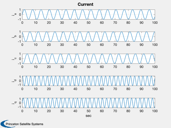
Finally, plot the time histories.
iL = {'i_a' 'i_b' 'i_c' 'i_d' 'i_q'};
Plot2D( t, [iAB;iDQ], 'sec', iL, 'Current')
%--------------------------------------
% PSS internal file version information
%--------------------------------------