Design and demonstrate a controller using QCR
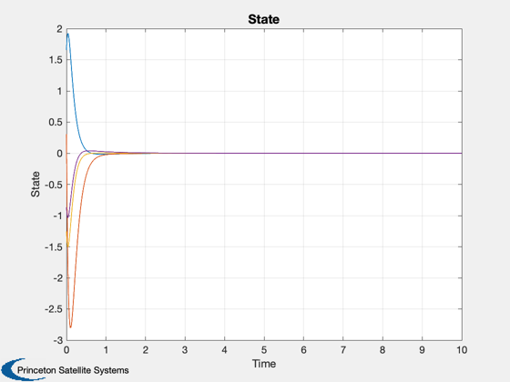
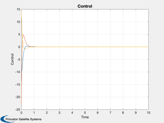
Design a multi-input / multi-output LQ controller using QCR with a state/input cross-coupling term. Simulate and plot the results.
------------------------------------------------------------------------
See also QCR
------------------------------------------------------------------------
Contents
%---------------------------------------------------------------------------
%   Copyright (c) 2012 Princeton Satellite Systems, Inc.
%   All rights reserved.
%---------------------------------------------------------------------------
Design the LQ controller
N=4; % # states
M=3; % # inputs

% Plant matrix
ra=randn(N);
a=ra'*ra;

% Input matrix
b=randn(N,M);

% QCR will create a regulator of the form "u = -Kx" to minimize the cost:
%   J = †{(1/2)[u'ru + x'qx] + u'nx + x'nu}dt.

% q: state penalty matrix
rq=randn(N);
q=rq'*rq;

% r: input penalty matrix
rr=randn(M,M);
r=rr*rr';

% n: state/input cross-coupling penalty matrix
n=randn(N,M);

% Design LQ controller
[K,sinf] = QCR(a,b,q,r,n);
Discretize system
dT = 1e-3;
[ak,bk] = C2DZOH(a,b,dT);
Simulate
nSim = 1e4;
x = zeros(N,nSim);
u = zeros(M,nSim);
x(:,1) = randn(N,1);
for k=1:nSim-1
  u(:,k) = -K*x(:,k);
  x(:,k+1) = ak*x(:,k) + bk*u(:,k);
end
Plot Time History
t = 0:dT:(nSim-1)*dT;
Plot2D(t,x,'Time','State')
Plot2D(t,u,'Time','Control')

%--------------------------------------
% $Date$
% $Id: fbc9bf1af14512d3d998a53d5eb4d63fb0097622 $

