Demonstrate disturbance modeling with shadowing.
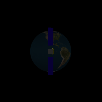
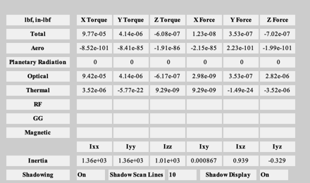
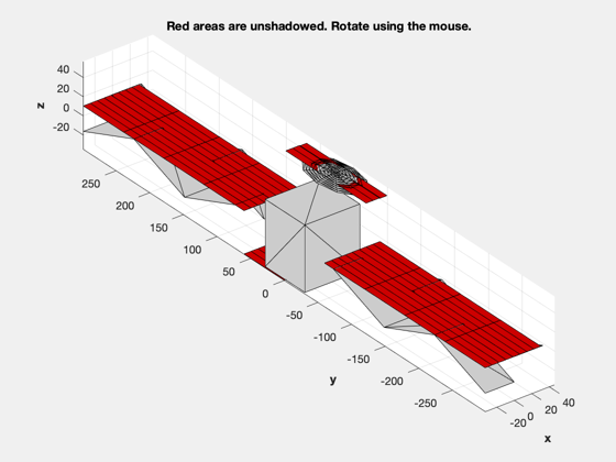
This example runs the disturbance model in single point mode, each call produces disturbance torques for a single point in time. You can run DrawSCPlugIn at the same time to make certain that the sun is in the right place and the spacecraft orientation and orbit are correct. ------------------------------------------------------------------------- See also BuildCADModel, CreateComponent, ArrayPatch, QForm, QLVLH, QPose, FindSolsticeOrEquinox, RVFromKepler, Disturbances, SunV1, DrawSCPlugIn -------------------------------------------------------------------------
Contents
%-------------------------------------------------------------------------------
%   Copyright (c) 1998-2003 Princeton Satellite Systems, Inc.
%   All rights reserved.
%-------------------------------------------------------------------------------
Parameters
% Spacecraft dimensions
xW               = 66/2;
yW               = 62/2;
zW               = 74/2;
Build the CAD model
BuildCADModel( 'initialize' );
BuildCADModel( 'set name' , 'Comsat' );
BuildCADModel( 'set units', 'in'     );

% Core
m              = struct();
m.name         = 'Core';
m.rHinge       = [0;0;0];
m.bHinge.b     = eye(3);
m.previousBody = [];
BuildCADModel('add body', m );

% Solar array
m.name         = 'South Solar Array';
m.rHinge       = [0 0 0]';
m.bHinge.b     = eye(3);
m.previousBody = 1;
BuildCADModel('add body', m );

m.name         = 'North Solar Array';
m.rHinge       = [0 0 0]';
m.bHinge.b     = eye(3);
m.previousBody = 1;
BuildCADModel('add body', m );

% This creates the connections between the bodies
BuildCADModel( 'compute paths' );

% The solar array when it is earth pointing
dArray          = struct();
dArray.z        = 76.25;
dArray.x        = 33;
dArray.nZ       = 3;
dArray.nX       = 2;
dArray.theta    = (10*pi/180)*[1 -1];

m               = ArrayPatch( dArray ); % Only use the front of the array
m.v(:,3)        = m.v(:,3) + dArray.z/2;
b               = [1 0 0;0 0 1;0 -1 0];

mass            = struct();
mass.mass       = 10/(9.806/0.0254);
mass.inertia    = diag([10 1 10]);
mass.cM         = [0;66;0];

magnetic        = struct();
magnetic.dipole = [0;5;0];

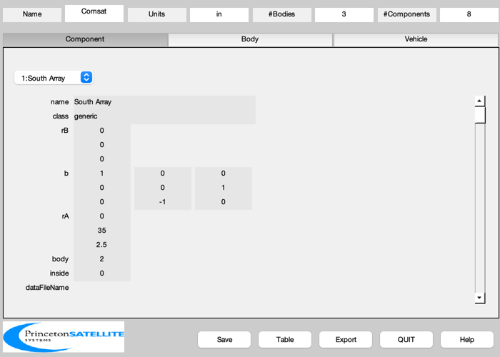
m = CreateComponent( 'make', 'generic', 'vertex', m.v, 'face', m.f, 'rA', [0 35 2.5]',...
                     'b', b, 'name', 'South Array', 'body', 2, 'mass', mass, ...
                     'faceColor', 'solar cell',...
                     'dipole', magnetic.dipole, 'inside', 0 );
BuildCADModel( 'add component', m );

mass.cM         = [0;-66;0];
m.v(:,3)        = - m.v(:,3);
m.f             = fliplr(m.f);

m = CreateComponent( 'make', 'generic', 'vertex', m.v, 'face', m.f, 'rA', [0 -35 2.5]',...
                     'b', b, 'name', 'North Array', 'body', 3, 'mass', mass, ...
                     'faceColor', 'solar cell',...
                     'dipole', magnetic.dipole, 'inside', 0 );
BuildCADModel( 'add component', m );

% Struts are added just for the picture They are 'inside' so they will not be
% considered in the disturbance analysis.
y       = 76.25/2;
w       = 11;
theta   = 10*pi/180;
b       =  1;
s       =  y*sin(theta)/2;
c       =  y*cos(theta);
m.v    = [    b   0   0;...
             -b   0   0;...
            w+b  -s   c;...
            w-b  -s   c;...
              b   0   0;...
             -b   0   0;...
          2*w+b  -s   c;...
          2*w-b  -s   c];

m.f    = [ 1  2  4  3;...
           5  6  8  7];

bStrut = [1 0 0;0 0 1;0 -1 0];

m = CreateComponent( 'make', 'generic', 'vertex', m.v, 'face', m.f, 'rA', [0 35 2.5]',...
                     'b', bStrut, 'name', 'South Array Strut 1', 'body', 2, 'mass', mass, ...
                     'faceColor', 'aluminum' );
BuildCADModel( 'add component', m );

m.v(:,3)    = -m.v(:,3);
m = CreateComponent( 'make', 'generic', 'vertex', m.v, 'face', m.f, 'rA', [0 -35 2.5]',...
                     'b', bStrut, 'name', 'North Array Strut 1', 'body', 3, 'mass', mass, ...
                     'faceColor', 'aluminum' );
BuildCADModel( 'add component', m );

m.v    = [    b   0   0;...
             -b   0   0;...
           -w+b   s   c;...
           -w-b   s   c;...
              b   0   0;...
             -b   0   0;...
         -2*w+b   s   c;...
         -2*w-b   s   c];

m.f         = [ 1  2  4  3;...
                5  6  8  7];

m = CreateComponent( 'make', 'generic', 'vertex', m.v, 'face', m.f, 'rA', [0 35 2.5]',...
                     'b', bStrut, 'name', 'South Array Strut 2', 'body', 2, 'mass', mass, ...
                     'faceColor', 'aluminum' );
BuildCADModel( 'add component', m );

m.v(:,3)    = -m.v(:,3);
m = CreateComponent( 'make', 'generic', 'vertex', m.v, 'face', m.f, 'rA', [0 -35 2.5]',...
                     'b', bStrut, 'name', 'North Array Strut 2', 'body', 3, 'mass', mass, ...
                     'faceColor', 'aluminum' );
BuildCADModel( 'add component', m );

% Core components
mass.mass       = 1000;
mass.inertia    = diag([1000 1000 1000]);
mass.cM         = [0;0;0];

magnetic.dipole = [5;5;5];
m = CreateComponent( 'make', 'box', 'x', 2*0.95*xW, 'y', 2*0.95*yW, 'z', 2*0.95*zW,...
                     'rA',[0;1;0],'name', 'Core Box', 'mass', mass, ...
                     'body', 1, 'inside', 0, ...
                     'faceColor', [0.7 0.7 0.7], 'edgeColor', [0.7 0.7 0.7],...
                     'dipole', magnetic.dipole );

BuildCADModel( 'add component', m );

rF         = struct();
rF.flux    = 600;
rF.u       = [0;0;1];
rF.r       = [0;0;0];
m = CreateComponent( 'make', 'ellipsoid', 'abc', [30 60 10], 'thetaUpper', pi/4,...
                     'n', 10, 'rA',[25;0;zW+10],'name', 'Elliptical reflector', ...
                     'faceColor', [0.5 0.5 0], 'edgeColor', [1 1 1],...
                     'body', 1, 'inside', 0, ...
                     'flux',rF.flux, 'u',rF.u, 'r',rF.r );

BuildCADModel( 'add component', m );

BuildCADModel( 'update body mass properties' );
BuildCADModel( 'create body arrays' ); % for shadowing

g = BuildCADModel('get model');
Simulation
% Ephemeris
jD0                    = FindSolsticeOrEquinox('spring equinox',2002);

nDays                  = 4;
nSamp                  = 200;
t                      = linspace(0,nDays,nSamp)*86400;
jD                     = jD0 + t/86400;

[rECI, vECI]           = RVFromKepler( [42167 0 0 0 0 0], t );

g.body(2).bHinge.angle = 0;
g.body(2).bHinge.axis  = 2;
g.body(3).bHinge.angle = 0;
g.body(3).bHinge.axis  = 2;

% Initialize the picture
g           = SetCADState(g,rECI(:,1), vECI(:,1));
g           = SetCADQuaternion(g,QLVLH(rECI(:,1), vECI(:,1)));
g.name      = 'ComStar';
tag3DWindow = DrawSCPlugIn( 'initialize', g, [], [], 'Earth', jD(1) );

% Disturbances
d             = Disturbances( 'defaults' );
solarFlux     = 1358;
d.s           = solarFlux*SunV1(jD(1)); % Watts/m^2
d.tSamp       = 10;
d.shadow      = 1;
d.showScans   = 1;
d.nScanLines  = 10;
d.units       = 'in';
d.planet      = 'earth';
d.mu          = 3.986014e5;
d.r           = rECI(:,1);
d.b           = [0;0;71]*1.e-9;
d.v           = vECI(:,1);
d.tGas        = 900;
d.mGas        = 0.02;
d.computePR   = 1;
d.computeAero = 1;

% Initialize the disturbance model
hD = Disturbances( 'init', g, d );

% Loop through the disturbances
TimeDisplay( 'initialize', 'SCDisturb', nSamp );
for k = 1:nSamp

  % Sun unit vector in the ECI frame
  uSun     = SunV1(jD(k));

  % CAD body structure
  g         = SetCADState(g,rECI(:,k), vECI(:,k));
  g         = SetCADQuaternion(g,g.qLVLH);
  uSunLVLH  = QForm( g.qLVLH, uSun );
  theta     = atan2( uSunLVLH(1), uSunLVLH(3) );
  g.body(2).bHinge.angle = -theta;
  g.body(3).bHinge.angle = -theta;

  % Draw the picture
  DrawSCPlugIn( 'update spacecraft', tag3DWindow, g, jD(k) );

  % Update the disturbances
  d.s    = 1367*uSun; % W/m^2
  d.r    = rECI(:,k);
  d.v    = vECI(:,k);
  [f, t] = Disturbances( 'run', g, d, hD );

  TimeDisplay( 'update' );
end

TimeDisplay( 'close' );

%--------------------------------------
                       ALim: [0 2]
                   ALimMode: 'auto'
                 AlphaScale: 'linear'
                   Alphamap: [1×64 double]
          AmbientLightColor: [1 1 1]
               BeingDeleted: off
                        Box: off
                   BoxStyle: 'back'
                 BusyAction: 'queue'
              ButtonDownFcn: ''
                       CLim: [0 255]
                   CLimMode: 'auto'
             CameraPosition: [-1.5348e+07 -5.7002e+07 12716]
         CameraPositionMode: 'manual'
               CameraTarget: [-1.0963e+07 -4.0717e+07 9082.9]
           CameraTargetMode: 'manual'
             CameraUpVector: [5.6053e-05 0.00020798 1]
         CameraUpVectorMode: 'manual'
            CameraViewAngle: 30
        CameraViewAngleMode: 'manual'
                   Children: [6×1 Graphics]
                   Clipping: on
              ClippingStyle: '3dbox'
                      Color: [0 0 0]
                 ColorOrder: [7×3 double]
            ColorOrderIndex: 1
                 ColorScale: 'linear'
                   Colormap: [256×3 double]
                ContextMenu: [0×0 GraphicsPlaceholder]
                  CreateFcn: ''
               CurrentPoint: [2×3 double]
            DataAspectRatio: [1 1 1]
        DataAspectRatioMode: 'manual'
                  DeleteFcn: ''
                  FontAngle: 'normal'
                   FontName: 'Helvetica'
                   FontSize: 10
               FontSizeMode: 'auto'
              FontSmoothing: on
                  FontUnits: 'points'
                 FontWeight: 'normal'
                  GridAlpha: 0.15
              GridAlphaMode: 'auto'
                  GridColor: [0.15 0.15 0.15]
              GridColorMode: 'auto'
              GridLineStyle: '-'
           HandleVisibility: 'on'
                    HitTest: on
              InnerPosition: [0 0 340 340]
               Interactions: [1×1 matlab.graphics.interaction.interface.DefaultAxesInteractionSet]
              Interruptible: on
    LabelFontSizeMultiplier: 1.1
                      Layer: 'bottom'
                     Layout: [0×0 matlab.ui.layout.LayoutOptions]
                     Legend: [0×0 GraphicsPlaceholder]
             LineStyleOrder: '-'
        LineStyleOrderIndex: 1
                  LineWidth: 0.5
             MinorGridAlpha: 0.25
         MinorGridAlphaMode: 'auto'
             MinorGridColor: [0.1 0.1 0.1]
         MinorGridColorMode: 'auto'
         MinorGridLineStyle: ':'
                   NextPlot: 'replace'
            NextSeriesIndex: 1
              OuterPosition: [-44.2 -37.4 416.5 402.9]
                     Parent: [1×1 Figure]
              PickableParts: 'visible'
         PlotBoxAspectRatio: [1.3811 3.7151 1]
     PlotBoxAspectRatioMode: 'auto'
                   Position: [0 0 340 340]
         PositionConstraint: 'innerposition'
                 Projection: 'perspective'
                   Selected: off
         SelectionHighlight: on
                 SortMethod: 'depth'
                        Tag: 'Spacecraft'
                    TickDir: 'out'
                TickDirMode: 'auto'
       TickLabelInterpreter: 'tex'
                 TickLength: [0.01 0.025]
                 TightInset: [0 0 0 0]
                      Title: [1×1 Text]
    TitleFontSizeMultiplier: 1.1
            TitleFontWeight: 'bold'
                    Toolbar: [1×1 AxesToolbar]
                       Type: 'axes'
                      Units: 'pixels'
                   UserData: []
                       View: [-62.829 0.080078]
                    Visible: off
                      XAxis: [1×1 NumericRuler]
              XAxisLocation: 'bottom'
                     XColor: [0.15 0.15 0.15]
                 XColorMode: 'auto'
                       XDir: 'normal'
                      XGrid: on
                     XLabel: [1×1 Text]
                       XLim: [-1.1239e+07 6378100]
                   XLimMode: 'auto'
                 XMinorGrid: off
                 XMinorTick: off
                     XScale: 'linear'
                      XTick: [1×9 double]
                 XTickLabel: {9×1 cell}
             XTickLabelMode: 'auto'
         XTickLabelRotation: 0
                  XTickMode: 'auto'
                      YAxis: [1×1 NumericRuler]
              YAxisLocation: 'left'
                     YColor: [0.15 0.15 0.15]
                 YColorMode: 'auto'
                       YDir: 'normal'
                      YGrid: on
                     YLabel: [1×1 Text]
                       YLim: [-4.1012e+07 6378100]
                   YLimMode: 'auto'
                 YMinorGrid: off
                 YMinorTick: off
                     YScale: 'linear'
                      YTick: [-40000000 -30000000 -20000000 -10000000 0]
                 YTickLabel: {5×1 cell}
             YTickLabelMode: 'auto'
         YTickLabelRotation: 0
                  YTickMode: 'auto'
                      ZAxis: [1×1 NumericRuler]
                     ZColor: [0.15 0.15 0.15]
                 ZColorMode: 'auto'
                       ZDir: 'normal'
                      ZGrid: on
                     ZLabel: [1×1 Text]
                       ZLim: [-6378100 6378100]
                   ZLimMode: 'auto'
                 ZMinorGrid: off
                 ZMinorTick: off
                     ZScale: 'linear'
                      ZTick: [1×7 double]
                 ZTickLabel: {7×1 cell}
             ZTickLabelMode: 'auto'
         ZTickLabelRotation: 0
                  ZTickMode: 'auto'
