An attitude and orbit simulation with reaction wheels.
This simulation includes reaction wheels with Coulomb friction and damping. It is easy to specify the damping terms for each wheel. The demo also includes the PID3Axis controller. The core dynamics is for a gyrostat orbiting around a point mass.
The simulation uses the vector pointing mode of PID3Axis to point a vector in the spacecraft frame either at nadir or at the sun.
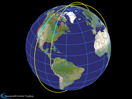
Control logic is included to point at nadir when the spacecraft is over the continental United States and at the sun otherwise.
------------------------------------------------------------------------
See also RHSSpacecraftWithRWA, PID3Axis, Plot2D, RK4
------------------------------------------------------------------------
Contents
%--------------------------------------------------------------------------
%   Copyright (c) 2017 Princeton Satellite Systems, Inc.
%   All rights reserved.
%--------------------------------------------------------------------------
%   Since version 2017.1
%--------------------------------------------------------------------------
Initialization
The RHS provides the default data structure for the model. Three orthogonal wheels are assumed. The default friction is zero for each wheel.
% Earth's radius
rE   = 6378.165;

% Simulation timing
tEnd = 10000.0; % sec
dT   = 1.0; % sec

% Initial Julian Date
jD0  = Date2JD([2020 4 5 0 0 0]);

% Spacecraft altitude
h         = 600.0; % km

% Data structure for the right hand side.
% Note non-spherical inertia matrix which results in cross-axis coupling.
d         = RHSSpacecraftWithRWA;
d.inr     = [3 0 0;0 10 0;0 0 5]; % kg-m^2
% Wheel inertia
d.inrRWA  = 1.5e-3*[1;1;1];  % kg-m^2

% Friction damping terms
% cDamping (viscous damping) should be on the order of 1e-6 Nms
% torqueCoulomb should be on the order of 1e-3 Nm
d.friction.cDampingRWA      = [5;5;5]*1e-6;      % Nms
d.friction.torqueCoulombRWA = [1;1;1]*1e-3;   % Nm

% Disturbance torque, Nm; try about 1-10e-5 Nm
d.torque = [0.0;0.0;0.0];

% Initial body rates, rad/s; try about 0.001 rad/s
wInit = [0.0;0;0.0];

% Initial wheel speeds
wRWA  = [0.0;0.0;0.0];
Design the controller
Use the PID3Axis function which handles updating the controller states.
dC                  = PID3Axis; % Gets the default data structure
dC.mode             = 1; % Vector tracking

% We specify a unit inertia so that the controller generates a control
% angular acceleration
inr   = 1.0;   % unit inertia
zeta  = 1.0;   % damping ratio
omega = 0.03;  % rad/sec
tauInt = 200;  % sec
omegaR = 0.05; % rad/sec
[dC.a, dC.b, dC.c, dC.d] = PIDMIMO(inr,zeta,omega,tauInt,omegaR,dT);
dC.body_vector  = [0;0;1];
Simulation
Perform a fixed step integration using RK4. The state vector includes the wheel speeds. The spacecraft is initialized in a circular orbit with zero rates.
% Steps
n         = ceil(tEnd/dT);

% State vector: [position;velocity;quaternion;body rate;rwa rate]
rInit     = (rE+h)*[cos(2);sin(2);0];
vInit     = [0;0;sqrt(d.mu/(rE+h))];
qInit     = [1;0;0;0];
x         = [rInit; vInit; qInit; wInit; wRWA];
rEF       = zeros(3,n);
xP        = zeros(length(x)+5,n);
t         = (0:n-1)*dT;
jD        = jD0 + t/86400;

% Create the area to be checked. Roughly covers CONUS.
m         = 100;
[lat,lon] = RAzToLatLon( 2000*ones(1,m), linspace(0,2*pi,m), pi/4, -1.1*pi/2 );

lat       = fliplr(lat);
lon       = fliplr(lon);
overA     = zeros(1,n);

for k = 1:n
  % Local variables
  r           = x( 1: 3);
  q           = x( 7:10);

  % ECI sun and Earth vectors
  bECIToEF    = EarthRot(JD2T(jD(k)));
  rEF(:,k)    = bECIToEF*r;

  j           = OverArea( rEF(:,k),lat,lon);
  if( j == 0 )
    dC.eci_vector = SunV1( jD(k));
  else
    dC.eci_vector = -Unit(r);
    overA(k) = 1;
	end

  % The PID controller
  [tRHS, dC]	= PID3Axis( q, dC );

  % Reaction wheel torque is on the left hand side
  d.torqueRWA = -d.inr*tRHS;

  % Pointing error
  arg         = dC.eci_vector'*QTForm( q, dC.body_vector );
  if( abs(arg) > 1 )
    arg = sign(arg);
  end
  pErr        = acos(arg);

  % Plot storage
  xP(:,k)     = [x;d.torqueRWA;j;pErr];

  % Right hand side
  x           = RK4(@RHSSpacecraftWithRWA,x,dT,0,d);
end
Plotting
[t,tL] = TimeLabl(t);
3D Plot
LoadEarthMap;
hold on
[~,rS] = OverArea( x(1:3), lat, lon );
plot3(rS(1,:),rS(2,:),rS(3,:),'color','r');
plot3(rEF(1,:),rEF(2,:),rEF(3,:),'color','y','linewidth',2);
kOver = find(overA>0);
plot3(rEF(1,kOver),rEF(2,kOver),rEF(3,kOver),'c.');
2D plots
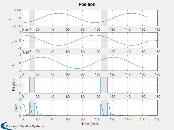
Position
k      = [1:3 20:21];
yL     = {'r_x', 'r_y', 'r_z' 'Region' 'Error'};
h(1) = Plot2D( t, xP(k,:),tL,yL,'Position');
AddFillToPlots(t,overA,h(1),[1 1 1;0.8 0.8 0.8],0.5)

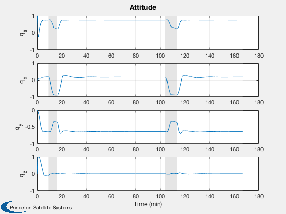
% Quaternion
k      = 7:10;
yL     = {'q_s', 'q_x', 'q_y', 'q_z'};
h(2) = Plot2D( t, xP(k,:),tL,yL,'Attitude');
AddFillToPlots(t,overA,h(2),[1 1 1;0.8 0.8 0.8],0.5)

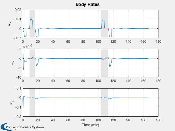
% Angular rate
k      = 11:13;
yL     = {'\omega_x', '\omega_y', '\omega_z'};
h(3) = Plot2D( t, xP(k,:),tL,yL,'Body Rates');
AddFillToPlots(t,overA,h(3),[1 1 1;0.8 0.8 0.8],0.5)

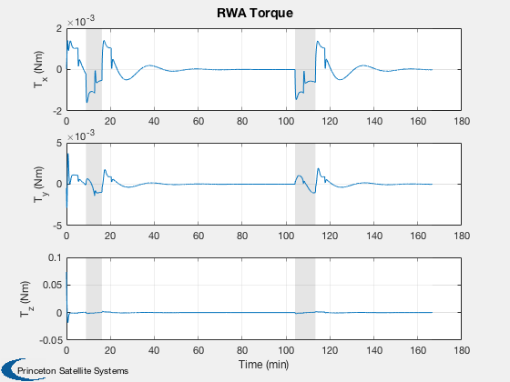
% Reaction wheel torque and rate
k      = 17:19;
yL     = {'T_x (Nm)', 'T_y (Nm)', 'T_z (Nm)'};
h(4) = Plot2D( t, xP(k,:),tL,yL,'RWA Torque');
AddFillToPlots(t,overA,h(4),[1 1 1;0.8 0.8 0.8],0.5)

k      = 14:16;
yL     = {'\omega_1', '\omega_2', '\omega_3'};
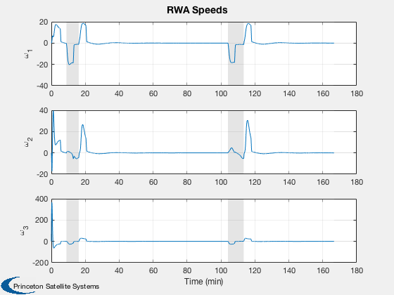
h(5) = Plot2D( t, xP(k,:),tL,yL,'RWA Speeds');
AddFillToPlots(t,overA,h(5),[1 1 1;0.8 0.8 0.8],0.5)

Figui;


%--------------------------------------
