Verify momentum conservation and rate adjustment for gimbal commands.
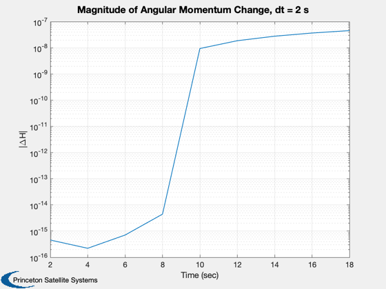
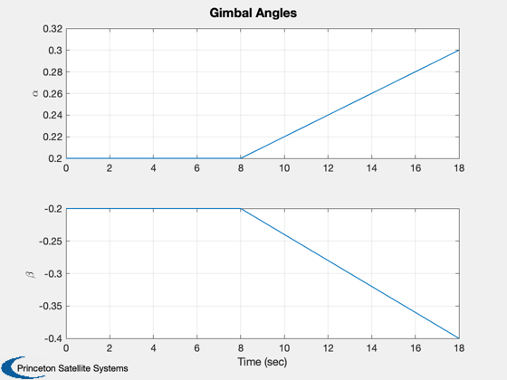
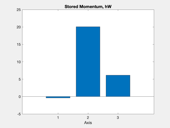
The CAD model has a flat plate sail with a rigid mast attached by two gimbals. The gimbals are modeled as achieving any commanded rate up to some maximum instantaneously. A momentum sink is used to isolate the boom motion from the core body rates. Angular momentum conservation is confirmed by using different time steps and confirming that a smaller time step results in a smaller momentum change over the course of the simulation.
Functions demonstrated:
    SailWithBoom.m / SailWithBoom.mat, the CAD model
    HGimballedBoom.m, angular momentum function
    TwoBodyRateModel.m, attitude dynamics integrated with RK4
Since version 7.
------------------------------------------------------------------------
See also Constant, NewFig, Plot2D, Mag, RK4, Unit, JD2000,
QSunPointing, SunVectorECI, HGimballedBoom
------------------------------------------------------------------------
Contents
%-------------------------------------------------------------------------------
%	Copyright (c) 2005 Princeton Satellite Systems, Inc.
%   All rights reserved.
%-------------------------------------------------------------------------------

%%%%%%%%%%%%%%%%%%%%%%%%%%%
%  User Parameters
%%%%%%%%%%%%%%%%%%%%%%%%%%%
dT    = 2;     % sec
aRate = 0.01; % rad/sec
%%%%%%%%%%%%%%%%%%%%%%%%%%%

clear f; clear tq;

%--------------------
Load the sail model
%--------------------
g          = load('SailWithBoom.mat');

%-------------------------------
Create the disturbance profile
%-------------------------------
Parameters for the orbit. We are creating a circular orbit.
%------------------------------------------------------------
r          = Constant('au'); % Radius in km
mu         = Constant('mu sun');
Initial Julian date
%--------------------
p        = [];
Orbit vector
%-------------
r0       = r*[1;0;0];
Quaternion (sun pointing)
%--------------------------
SunVectorECI( 'initialize', 'sun' );
rSunECI  = SunVectorECI( 'update', JD2000, r0 );
q        = QSunPointing( Unit(rSunECI) );

% Gimbal angles. The sail is two body with a gimbaled boom
% The first angle is the one nearest the core
% The axes correspond to the angles
% The body array says each gimbal is at the joint between the
core and the boom. The core is defined as body 1 in the CAD file
%-----------------------------------------------------------------
p.angle    = [0;0];
p.axis     = [1 0;0 1;0 0];
p.body     = [2 2];
Sim timing
%-----------
nSim = 10;
t    = 0;
Initial state
%--------------
w     = 0.001*[-0.4;-1.6;0.1];
angle = [0.2;-0.2];
aDot  = [0;0];
x     = [q;w;angle;aDot];
hW    = [0;0;0];

tPlot = zeros(1,nSim);
xPlot = zeros(length(x),nSim);
hPlot = zeros(3,nSim);

for k = 1:nSim

  % Store data in plots
  %--------------------
  tPlot(k)   = t;
  xPlot(:,k) = x;

  % Compute the disturbances.
  %--------------------------
  f.totalBody = zeros(3,1,2);
  tq.totalBody = zeros(3,1,2);

  % Boom control
  %-------------
  if (k == 5)
    aDot = aRate*[1;-2];
    % Find angular momentum to be absorbed
    [hT, hW] = HGimballedBoom( [zeros(6,1);x], g, p.axis, aDot, hW );
    x(10:11) = aDot;
  end

  % Calculate momentum
  %-------------------
  hPlot(:,k) = HGimballedBoom( [zeros(6,1);x], g, p.axis, [], hW );

  % RHS
  %----
  x = RK4( 'TwoBodyRateModel', x, dT, t, f, tq, g, p, hW );

  % Update time
  %------------
  t    = t + dT;

end

dH = hPlot-repmat(hPlot(:,1),1,nSim);
Plot2D(tPlot,Mag(dH),'Time (sec)','|\DeltaH|',['Magnitude of Angular Momentum Change, dt = ' num2str(dT) ' s'],'ylog')
Plot2D(tPlot,xPlot(8:9,:),'Time (sec)',{'\alpha','\beta'},'Gimbal Angles')
NewFig('Momentum'); bar(hW);
xlabel('Axis')
title('Stored Momentum, hW','fontsize',14,'fontweight','bold')


%--------------------------------------
% PSS internal file version information
%--------------------------------------