Contents
- Test a sun and earth sensor attitude determination system.
- Constants
- Simulation data
- Spacecraft data
- Column 1 is the earth sensor, Column 2 is the sun sensor
- Set up plotting arrays
- Control system initialization
- Generate the orbit
- Initial conditions at equinox
- Sun and earth vectors
- Initial state
- Run the simulation
- Plot results
Test a sun and earth sensor attitude determination system.
dT is the time step for the attitude determination system. You can numerically integrate with a smaller time step by setting nInt > 1. The initial attitude is unknown. This demo uses the sun and the earth as attitude sources. The earth provides roll and pitch while the sun provides yaw.
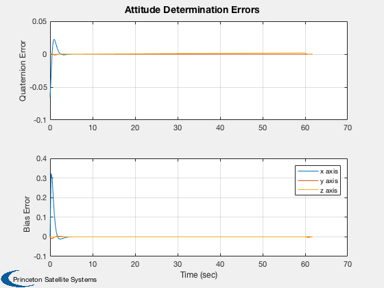
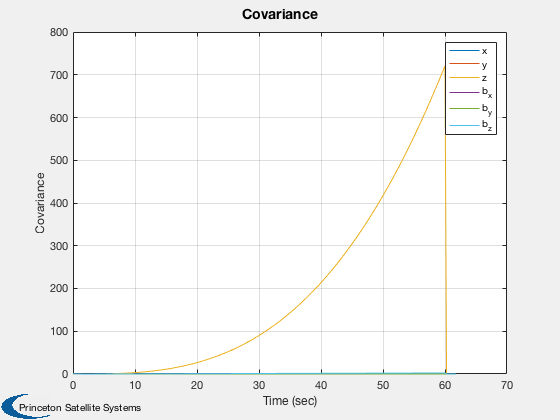
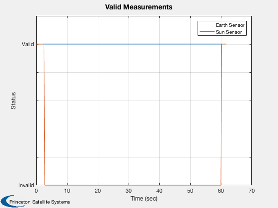
The simulation starts with valid measurements from both sun and earth sensors. The attitude and rate errors rapidly go to zero. The spacecraft has a small z rate so eventually the sun sensor measurement is no longer valid. The covariance then grows rapidly. Note that the plant noise covariances are larger than the measurement covariances. This determines the rate of growth. When the sun is visible again, the covariance drops. Eclipses are not modeled which would cause additional sun sensor outages.
%--------------------------------------------------------------------------
%  See also QLVLH, QMult, QPose, QUnit, Plot2D, TimeGUI, RK4, Unit,
%  Date2JD, SunEarthAttDet, TOrbit, RVFromKepler, SunV1, FPSensors, RIGOut
%  TimeLabl
%--------------------------------------------------------------------------
%--------------------------------------------------------------------------
%   Copyright (c) 1994-2000, 2017 Princeton Satellite Systems, Inc.
%   All rights reserved.
%--------------------------------------------------------------------------
%   2017.1 Changed the simulation duration and initial conditions
%--------------------------------------------------------------------------

rng('default');
Constants
degToRad = pi/180;
Simulation data
nInt = 2;
Spacecraft data
inr      = [1000 0 0;0 2000 0; 0 0 2000];
invInr   = inv(inr);
torque   = zeros(3,1);

% Sensor data. The sensor boresights are their z axes
Column 1 is the earth sensor, Column 2 is the sun sensor
qBToS   = [1 cos(pi/4);0 0;0 sin(pi/4);0 0];
dQ      = [0;0;0.1;0.1];
fov     = [30 30;30 30]*degToRad;
fScale  = 1;

% Time
tEnd    = 62;
t       = 0;
dT      = 0.25;
nSim    = tEnd/dT;
Set up plotting arrays
xPlot     = zeros(13,nSim);
qPlot     = zeros( 4,nSim);
pPlot     = zeros( 6,nSim);
bPlot     = zeros( 3,nSim);
aPlot     = zeros( 3,nSim);
tPlot     = zeros( 1,nSim);
qEPlot    = zeros( 4,nSim);
vMPlot    = zeros( 2,nSim);

% Set up simulation vectors
angInc    = zeros(3,1);
xRIGOld   = zeros(3,1);
nRWRIG    = zeros(3,1);
nBRIG     = zeros(3,1);
nORIG     = zeros(3,1);
betaRIG   = zeros(3,1);
uRIG      = eye(3);
Control system initialization
b         = zeros(3,1);
p         = eye(6);
Q         = 0.01*eye(6);
r         = 0.0001;
Generate the orbit
tOrbit    = (0:(nSim-1))*dT;

% el = [a,i,W,w,e,M]. The spacecraft is in geosynchronous orbit
[rECI, vECI] =  RVFromKepler( [42167 0 0 0 0 pi/2], tOrbit );
Initial conditions at equinox
jD = Date2JD([2000 3 20 7 26 0]) + (tOrbit + 6*3600)/86400;
Sun and earth vectors
uNadir = -Unit( rECI );
uSun   =  SunV1( jD, rECI );
Initial state
omega   = [0;0;0.1];
bias    = [-0.0001; -0.0001;  0.000];
intRate	= [0;0;0];

qSim    = QLVLH(rECI(:,1),vECI(:,1));
% Quaternion, body rates, integrated rate, gyro biases
x       = [qSim; omega; intRate; bias];

% Estimated quaternion
q       = QUnit(qSim + dQ);
Run the simulation
for k = 1:nSim

	% Quaternion
  qSim              = x(1:4);

  % Attitude Determination
  catalog          = [uNadir(:,k) uSun(:,k)];
  sensorData       = FPSensors( qSim, qBToS, catalog, fov, fScale );
  [angInc,xRIGOld] = RIGOut( x(8:10), xRIGOld, nORIG );
  [q,b,p]          = SunEarthAttDet( angInc, q, dT, b, p, Q, r, qBToS, sensorData, catalog, fScale );
  err_x_q_b        = [QMult( QPose(q), qSim ), qSim, q, [0;b], [0;x(11:13)]];

  % Plotting
  qPlot(:,k)       = err_x_q_b(:,1);
  pPlot(:,k)       = diag(p);
  bPlot(:,k)       = b;
  xPlot(:,k)       = x;
  aPlot(:,k)       = angInc;
  vMPlot(:,k)      = sensorData.valid;
  tPlot(k)         = t;
  qEPlot(:,k)      = q;

  % Simulation
  for j = 1:nInt
    x      = RK4( @FRBwRIG, x, dT/nInt, t, inr, invInr, torque, uRIG, nRWRIG, nBRIG, betaRIG );
    x(1:4) = QUnit(x(1:4));
    t      = t + dT/nInt;
  end
end
Plot results
j       = 1:k;
[t,tL]  = TimeLabl(tPlot(j));
yL      = {'Quaternion Error' 'Bias Error'};

Plot2D( t, [qPlot(2:4,j);xPlot(11:13,j)-bPlot(:,j)],tL,yL,'Attitude Determination Errors','lin',['1:3';'4:6'])
legend('x axis','y axis','z axis')

yL = {'True' 'Estimated'};
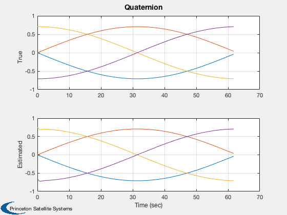
Plot2D( t, [xPlot(1:4,j);qEPlot(:,j)],tL,yL,'Quaternion','lin',['1:4';'5:8'])
Plot2D( t, pPlot(:,j),tL,'Covariance','Covariance')
legend('x','y','z','b_x','b_y','b_z');

Plot2D( t, vMPlot(:,j),tL,'Status','Valid Measurements')
legend('Earth Sensor','Sun Sensor')

% Making the axis labels easier to understand
set(gca,'ylim',[0 1.2]);
set(gca,'yticklabel',{'Invalid' '' '' '' '' 'Valid' ''});

%--------------------------------------


