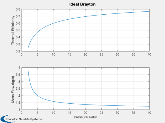
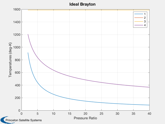
Analysis of an ideal Brayton cycle
Assumes the compressor and turbine are 100% efficient. The cycle points are:
1 - compressor inlet
2 - compressor outlet
3 - turbine inlet
4 - turbine outlet
Note: t2 = t4 in this ideal cycle.
See also BraytonIdeal
%--------------------------------------------------------------------------
%   Copyright (c) 2016 Princeton Satellite Systems, Inc.
%   All rights reserved.
%--------------------------------------------------------------------------
%   Since 2017.1
%--------------------------------------------------------------------------

% The working fluid is Helium
name  = 'He';
gamma = 1.659;   % Ratio of specific heats
cP    = 5190;    % Thermal capacity (J/kg-deg-K)

% Look at a range of pressure ratios
pR    = [linspace(2,10,50) linspace(10.1,40,50)];

% Input power
qR    = 7.8e6;

% Temperature at compressor (selected according to operating temperature of
% General Electric Ceramic Matrix Composite (CMC) turbine blades)
% "SiC CMCs can withstand temperatures greater than 2400 F/1316 C"
t3    = 1316 + 273; % convert C to deg-K

% Calculate the ideal Brayton cycle and plot
[eff, mDot, t] = BraytonIdeal( gamma, pR, cP, t3, qR );

Plot2D( pR, [eff;mDot], 'Pressure Ratio', {'Thermal Efficiency' 'Mass Flow (kg/s)'}, 'Ideal Brayton' );
Plot2D( pR, t, 'Pressure Ratio', 'Temperatures (deg-K)', 'Ideal Brayton' );
legend('1','2','3','4');


%--------------------------------------

